In recent years, there has been a move to develop and apply contactless IC cards to gradually replace contact IC cards. RFID (Radio Frequency Identification) cards are a typical example of contactless IC cards. However, RFID requires different antenna communication technologies for data exchange in various application environments.
Since the first IC card was introduced in 1970, it has become one of the fastest-growing products in the microelectronics market, with over 700 million IC cards sold worldwide by 1996. However, contact-based IC cards have inherent disadvantages, such as poor resistance to corrosion and contamination at contact points, which significantly reduces their lifespan and usability. In recent years, there has been a shift toward developing contactless IC cards to gradually replace contact-based ones. RFID (Radio Frequency Identification) cards are a typical example of contactless IC cards, using wireless communication technology for data exchange between the system and the IC card, offering greater convenience than traditional contact-based cards. They have been widely used for electronic tags and identity cards. However, RFID requires different antenna communication technologies for data exchange in various application environments. We will first explain the basic working principles of RFID application systems to illustrate that antenna design is key to different RFID applications. Then, we will introduce several typical RFID antennas and their design principles, hoping to assist everyone.
1.RFID Technology Principles
Typically, an RFID application system consists of two main parts: the reader/writer and the RFID card. The reader/writer usually functions as a computer terminal, facilitating data reading, writing, and storage for RFID cards. It is composed of a control unit, a high-frequency communication module, and an antenna. The RFID card is a passive responder, mainly consisting of an integrated circuit (IC) chip and its external antenna. The RFID chip typically integrates circuits for the radio frequency front end, logic control, and memory, with some even having the antenna integrated onto the same chip.

he basic working principle of an RFID application system is that when an RFID card enters the radio frequency field of the reader/writer, the card’s antenna captures the induced current, which is then boosted to power the chip. Simultaneously, the induced current carrying information is processed through the radio frequency front-end circuit, converting it into a digital signal that is sent to the logic control circuit for information processing. The required response information is retrieved from the memory and sent back through the logic control circuit to the radio frequency front-end circuit, ultimately being transmitted back to the reader/writer via the antenna.
It is clear that the antenna plays a critical role in the data communication process between the RFID card and the reader/writer. On one hand, the passive RFID card chip needs to obtain sufficient energy from the electromagnetic field generated by the reader’s antenna to activate its circuit. On the other hand, the antenna determines the communication channel and method between the RFID card and the reader/writer.
Currently, RFID has been widely adopted and has several international standards, including ISO 10536, ISO 14443, ISO 15693, and ISO 18000. These standards not only specify communication data frame protocols but also focus on regulating technical specifications related to physical characteristics of antennas, such as operating distance, frequency, and coupling methods. The establishment of standards for RFID application systems determines the selection of RFID antennas. Below, we will introduce various types of RFID antennas that have been widely used, along with their performance characteristics.
2.RFID Antenna Types
RFID antennas mainly come in three basic forms: coil-type, microstrip patch-type, and dipole-type. For near-range applications (less than 1 meter), RFID antennas typically use simple and low-cost coil-type antennas, which mainly operate in the medium to low frequency range. For long-range applications (over 1 meter), microstrip patch-type or dipole-type RFID antennas are required, operating in high frequency and microwave bands. Each of these antenna types operates on different principles.
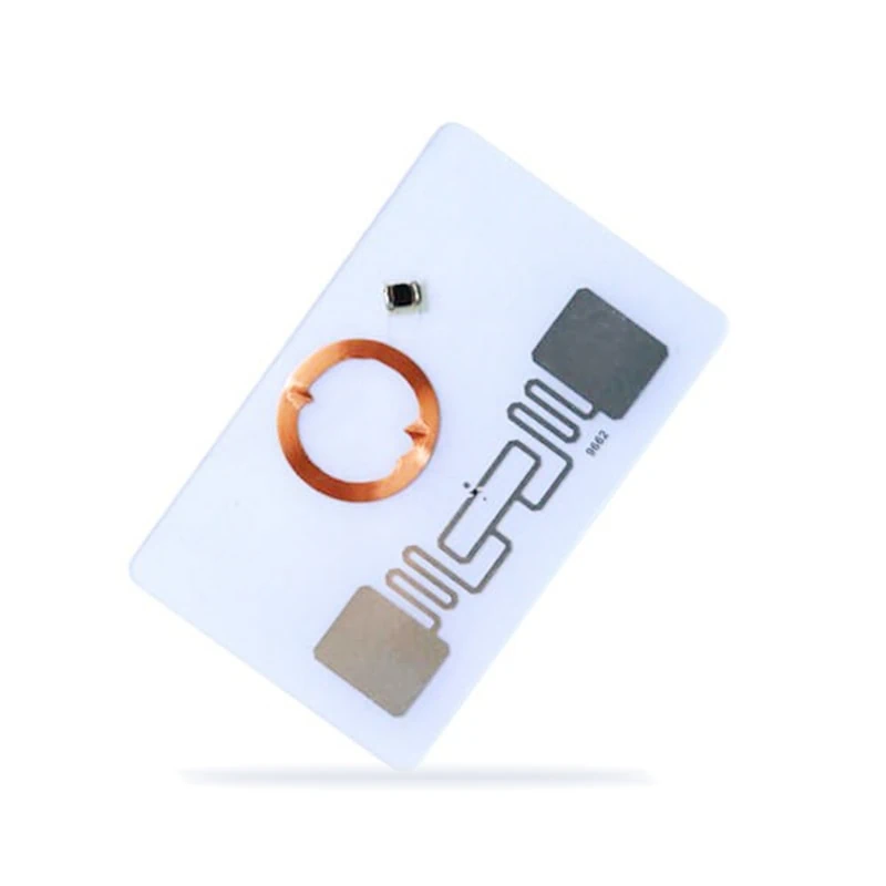
2.1 Coil Antennas

-
When the RFID coil antenna enters the alternating magnetic field generated by the reader, the interaction between the RFID antenna and the reader antenna resembles that of a transformer, where the coils act as the primary and secondary windings. The resonant circuit formed by the RFID coil antenna includes the coil inductance LLL, parasitic capacitance CpC_pCp, and parallel capacitance C2′C’_2C2′. The RFID application system achieves bidirectional data communication through this frequency carrier. Commonly used ID1-type contactless IC cards are small plastic cards (85.72 mm × 54.03 mm × 0.76 mm), with a resonant working frequency of 13.56 MHz. Currently, short-range RFID application systems with coil antennas as small as 0.4 mm × 0.4 mm have been developed.
Some applications require the RFID antenna coil to be very compact while maintaining a certain operating distance, such as in animal identification. If the coil area is too small, the mutual inductance MMM between the RFID and reader antennas will not meet practical requirements. To address this, ferromagnetic materials with high magnetic permeability μ\muμ are often inserted into the RFID antenna coil to increase mutual inductance, compensating for the reduction in coil cross-section.
2.2 Microstrip Patch Antennas

-
Microstrip patch antennas consist of a radiating patch conductor mounted on a dielectric substrate with a metal ground plane. Depending on the desired radiation characteristics, the patch conductor can be designed in various shapes. Typically, the distance between the radiating conductor and the metal ground plane is a fraction of the wavelength. If we assume that the electric field radiating along the transverse and longitudinal directions of the conductor remains unchanged, it varies primarily along the length of the conductor, approximately half a wavelength (λg/2\lambda_g / 2λg/2). The radiation from microstrip patch antennas is mainly due to the edge fields at the open edges of the patch conductor, providing a well-defined radiation direction. Therefore, they are generally suitable for RFID application systems where communication direction is relatively stable.
To enhance antenna performance and address directional communication issues, various types of microstrip slot antennas have been developed. For instance, a single-slot antenna operating at 24 GHz and a dual-slot antenna at 5.9 GHz, both radiating linearly polarized waves, have been designed. Additionally, a circularly polarized slot-coupled patch antenna has been created, capable of using left-handed and right-handed circular polarization to encode binary data as ‘1’ and ‘0’.
2.3 Dipole Antennas

-
In long-distance coupling RFID application systems, the most commonly used type is the dipole antenna (also known as a symmetrical dipole antenna). A dipole antenna consists of two straight conductors of equal thickness and length arranged in a straight line, with the signal fed into the two endpoints in the middle. This configuration creates a certain current distribution along the two arms of the dipole, which in turn generates an electromagnetic field in the surrounding space.
When the length lll of a single dipole arm is λ/4\lambda/4λ/4 (a half-wave dipole), the reactive component of the input impedance is zero, allowing the antenna’s input impedance to be considered a pure resistance. Ignoring the effects of the antenna’s thickness, a simple dipole antenna design can take the length lll as an integer multiple of λ/4\lambda/4λ/4. For example, a half-wave dipole antenna operating at a frequency of 2.45 GHz would have a length of approximately 6 cm. If a larger input impedance is required, a folded dipole design (as shown in Figure 4b) can be utilized.
3.RFID Antenna Design
From the introduction to RFID technology principles and antenna types, it’s clear that the key to specific RFID applications lies in the characteristics and performance of RFID antennas. Currently, the implementation technology for coil antennas is well-established, and they are widely used in applications such as identity recognition and item tagging. However, for RFID applications that require high frequencies, large data capacity, and uncertain working distances and directions, designing coil antennas to meet these performance criteria can be challenging.
Similarly, while microstrip patch antennas can be effective, their complex manufacturing processes and higher costs make them less suitable for low-cost RFID applications at this time. Dipole antennas, on the other hand, offer strong radiation capabilities, simple manufacturing, and low cost, making them ideal for RFID applications that require omnidirectional communication.
In summary, RFID technology has evolved significantly since the introduction of IC cards, providing innovative solutions for various applications. The choice of antenna type—be it coil, microstrip patch, or dipole—plays a crucial role in the performance of RFID systems. While coil antennas are well-suited for low-cost applications, the versatility and efficiency of dipole antennas make them ideal for more demanding environments. As RFID continues to advance, understanding these elements will be vital for developing effective and reliable systems that meet diverse needs across industries.